SLED16X5
Das Sockelprofil SLED16X5 stellt einen dezenten und innovativen Abschluss von Bodenbelag zu Wand, Fenster(rahmen) oder Treppenstufe her – dort, wo Anschluss- und Dehnfugen bautechnisch eingehalten werden müssen.
Geeignet für:
Parkett, Laminat, Designböden und Fliesen – ab einer Bodenstärke von 5 mm


LED-Beleuchtung
Für die LED-Beleuchtung können alle handelsüblichen LED-Stripes eingesetzt werden:
![]() Bei der horizontalen Montage der LED-Einheiten können LED-Stripes bis 8 mm Breite verwendet werden.
Bei der horizontalen Montage der LED-Einheiten können LED-Stripes bis 8 mm Breite verwendet werden.
![]() An der schrägen Innenseite der Leiste können LED-Stripes bis 12 mm Breite montiert werden.
An der schrägen Innenseite der Leiste können LED-Stripes bis 12 mm Breite montiert werden.
Das Sockelprofil SLED16X5 kann außerdem mit oder ohne LED-Einheit als Kabelkanal verwendet werden.
LED-Stripes sind nicht im Lieferumfang enthalten.
Smarte Beleuchtungsgeometrie
Das Sockelprofil SLED16X5 erschafft auf einfachste Art und Weise ein dezentes Lichtambiente: Eine homogene Lichtlinie trennt bei eingeschalteter LED-Beleuchtungseinheit optisch die Leiste von der Wand. Klassische LED-Abdeckprofile aus Kunststoff werden nicht benötigt und beeinträchtigen somit auch nicht im ausgeschalteten Zustand die Optik.
Das Sockelprofil SLED16X5 kann natürlich auch ohne LED-Einheit verwendet werden.
Durch die geneigte Außenfläche kann sich nahezu kein Staub auf dem Profil ablagern.

Silber seidenmatt EV1
Titan seidenmatt C31

Schwarz seidenmatt C35

Weiß feinstrukturiert RAL 9016

Gold seidenmatt EV3

Werkzeuglos, schnell und einfach
Unser Abschlussprofil SLED16X5 lässt sich einfach, werkzeuglos und ohne sichtbare Befestigungspunkte montieren: Kein Bohren, kein Schrauben, kein Hämmern, kein Dreck, kein Lärm, kein Ärgern. Unregelmäßigkeiten im Mauerwerk lassen sich leicht ausgleichen, indem Sie bei Bedarf einfach zusätzliche Montageclips anbringen.
Einfache Montage in nur 8 Schritten
Schritt 1
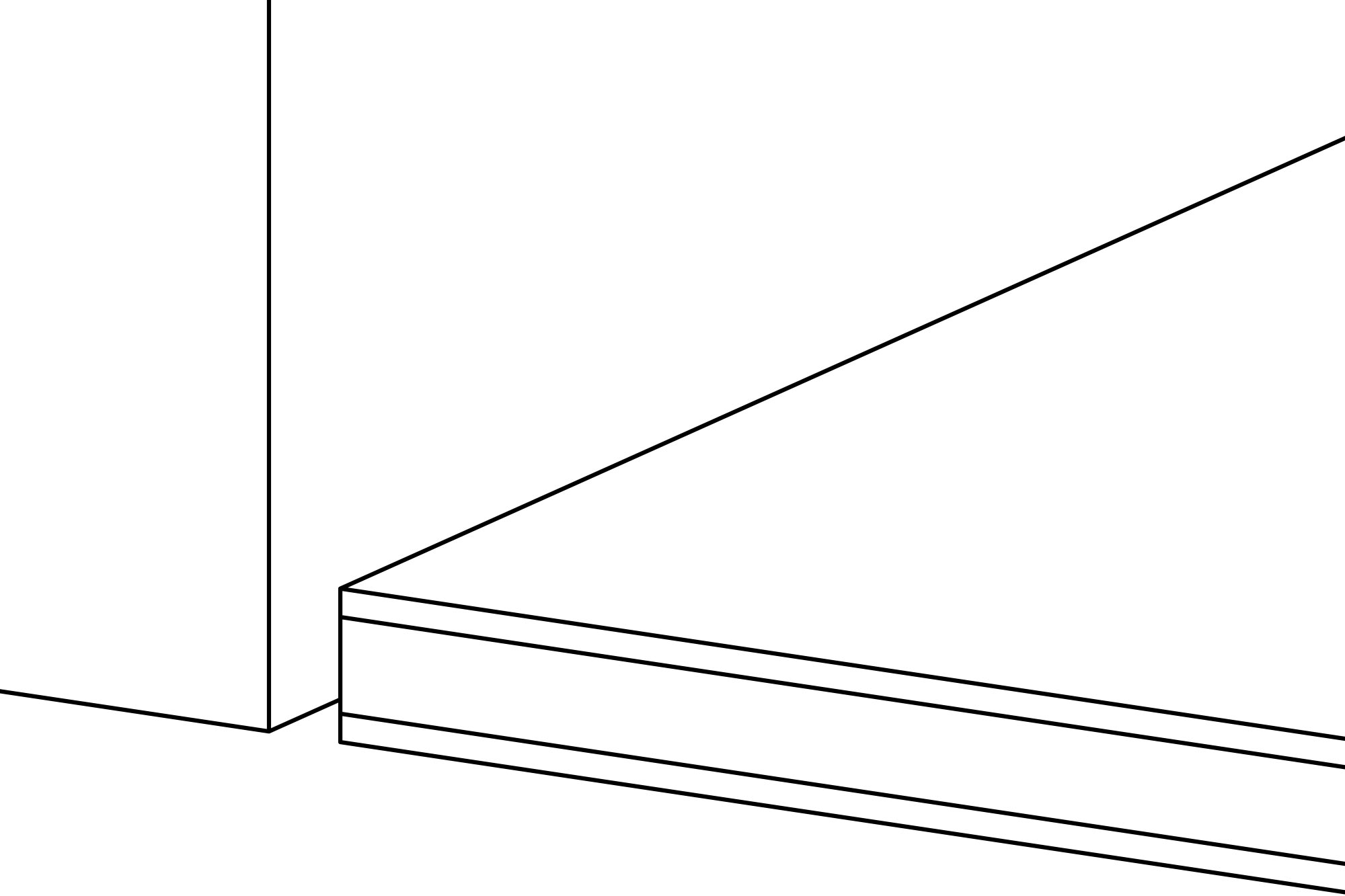
Die Breite der Anschlussfuge sollte je nach verwendetem Abschlusssystem zwischen 5 und 13 mm sein (siehe Datenblätter). Ebenfalls zu berücksichtigen ist die Stärke des Bodenbelags. Unsere Systeme des Typs X5 können bereits ab einer minimalen Bodenbelagsstärke von 5 mm eingesetzt werden.
Schritt 2
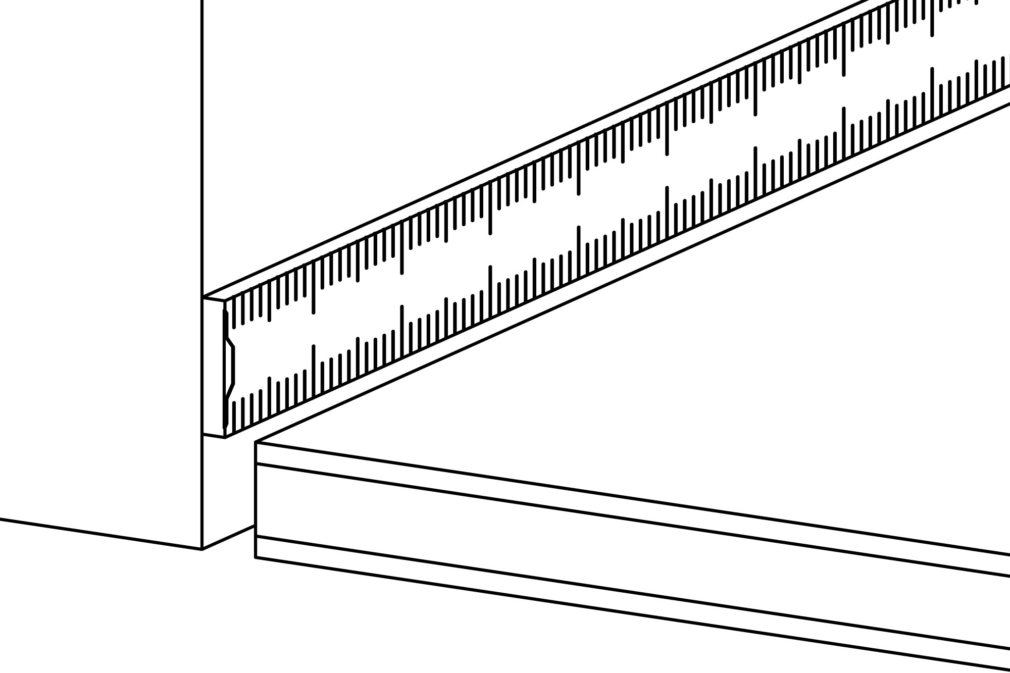
Die Abmessungen für die Profilzuschnitte werden an den Wandflächen abgenommen. Gehrungsschnitte für Innen- und Außenecken werden hierbei berücksichtigt.
Schritt 3
Die Profile werden passend abgelängt. Hierbei wird in einem Arbeitsgang der Gehrungsschnitt für Innen- oder Außenecke angebracht. Das Profil wird dabei sicher auf einen Holzträger gedrückt und in der Säge schnittgerecht positioniert. Die Schnittrichtung der Säge drückt dabei das Profil beim Schneidevorgang an den Holzträger.
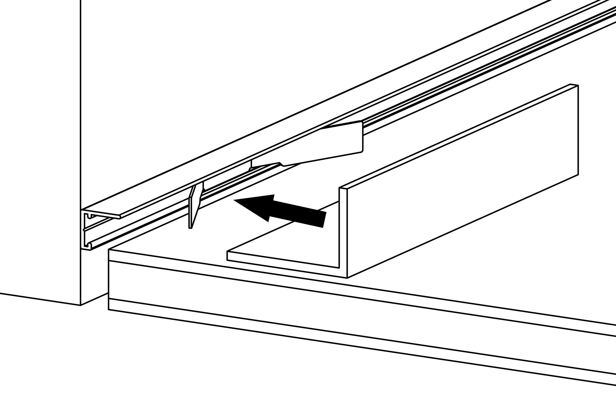
Schritt 4
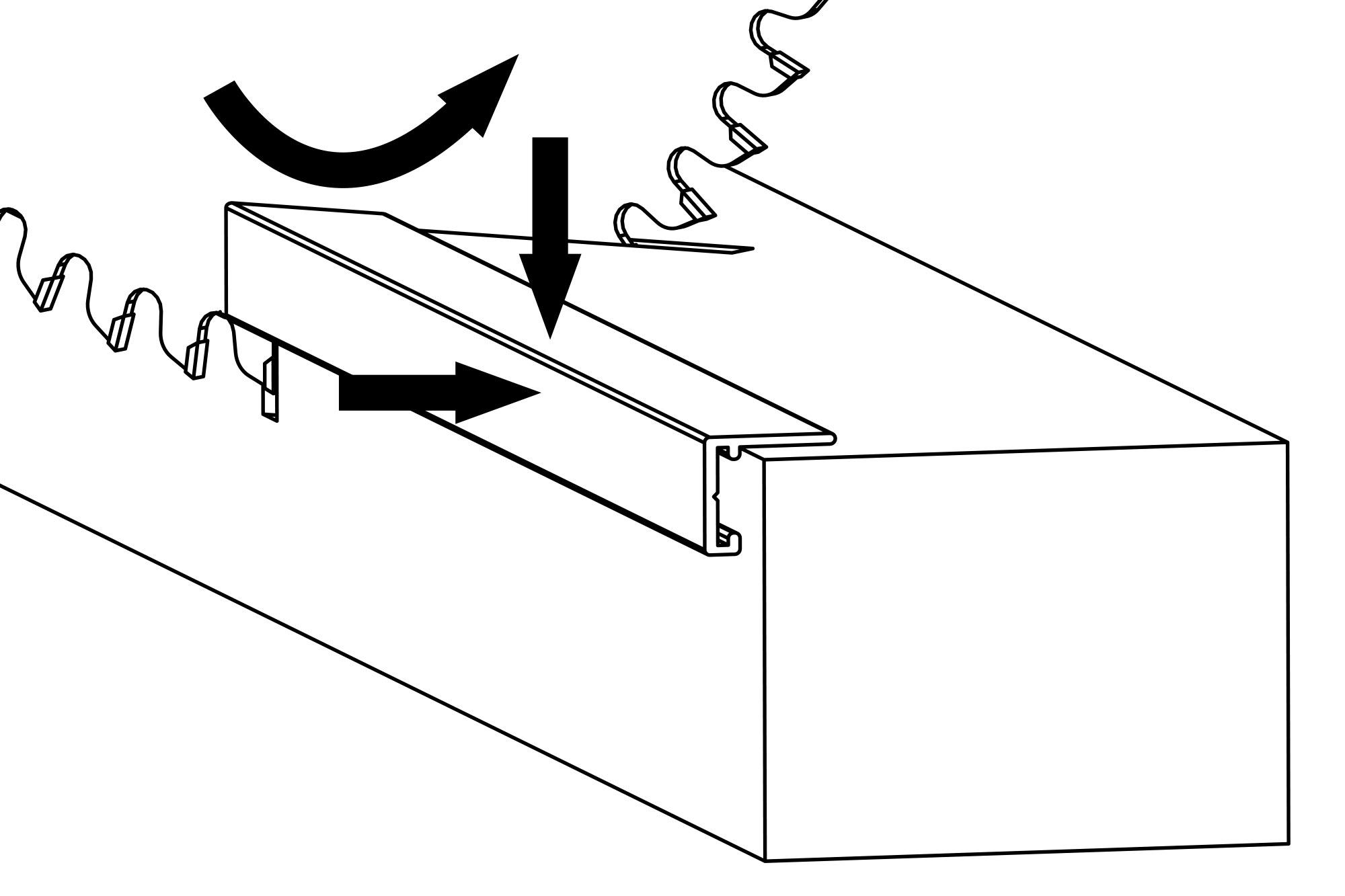
Die Montageclips werden stirnseitig in die Abschlussleiste eingeschoben. Achtung: In der Abschlussleiste sind zwei gegenüberliegende Absätze eingearbeitet, zwischen denen die Montageclips leichtgängig geführt werden.
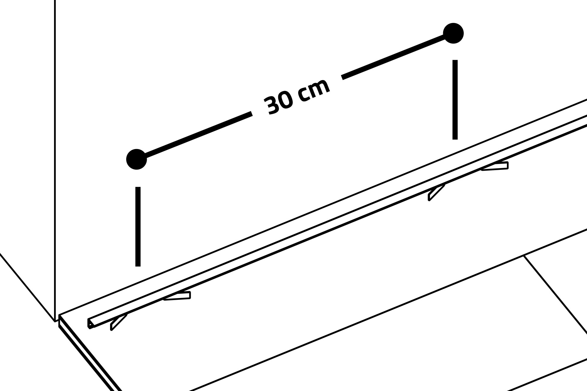
Schritt 5
Die Montageclips sollten in einem Abstand von etwa 30 bis 60 cm zueinander in die Abschlussleiste eingeschoben werden. Je nach Unebenheiten im Mauerwerk können einzelne Montageclips in engeren Abständen installiert werden, damit die Abschlussleiste flächenbündig am Mauerwerk anliegt.
Schritt 6
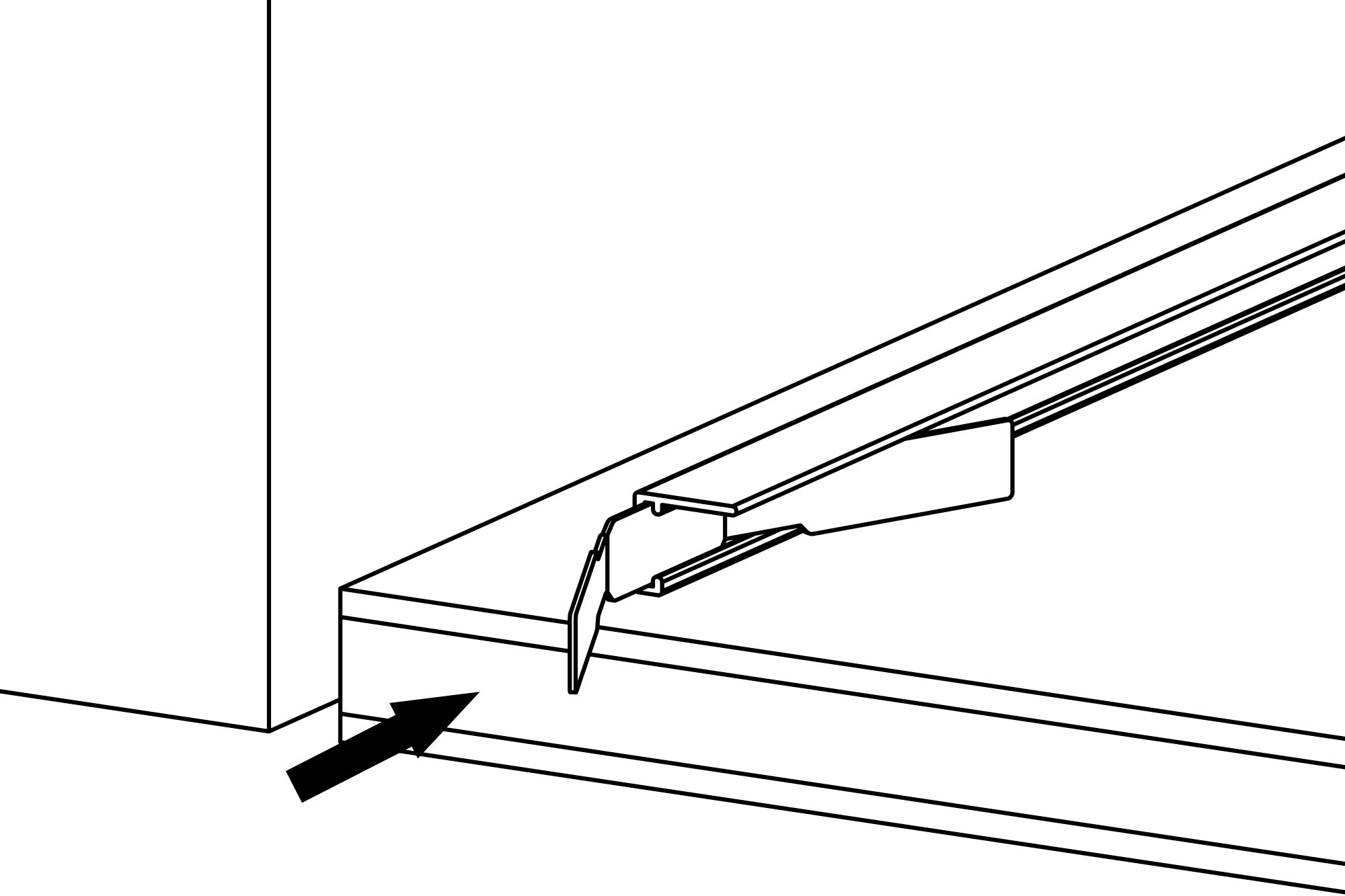
Die Abschlussleiste mit den eingeschobenen Montageclips wird nun an der Wandfläche in Montageposition gebracht. Mit der Montagehilfe werden die Montageclips vorsichtig aufgespreizt, indem mit der Montagehilfe die Montageclips Richtung Wand beaufschlagt werden.
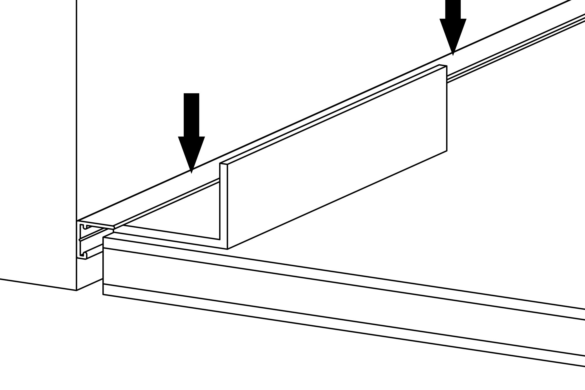
Schritt 7
Sobald der Spannvorgang abgeschlossen ist, wird die Abschlussleiste nach unten gedrückt und die Montagehilfe abgezogen. Nun wiederholt sich der Spann- und Montagevorgang, bis alle Montageclips einer Abschlussleiste gespannt und versenkt sind. Zu evtl. Korrekturen kann die Abschlussleiste jederzeit aus der Anschlussfuge entnommen werden.
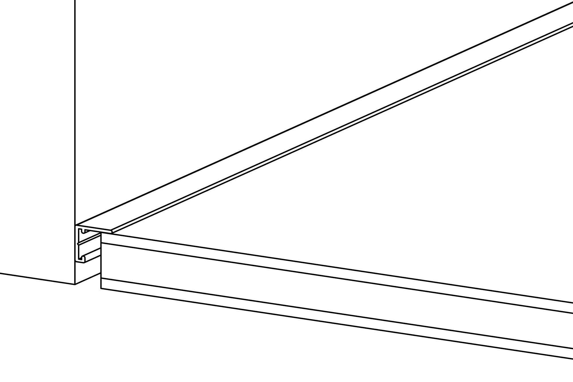
Schritt 8
Die Abschlussleiste ist montiert. Nach einer kurzen Kontrolle kann das nächste Teilstück montiert werden.

Kataloge und Datenblätter im Downloadbereich
Hier finden Sie alle wichtigen Informationen zum Download: Produktkatalog, Datenblätter, Montagehinweise etc.
Jetzt unverbindliches Angebot anfordern
Haben wir Ihr Interesse geweckt und wünschen Sie ein persönliches Angebot? Wir freuen uns auf Ihre Anfrage.
Angebotsanfrage DE
minileiste by ENGELTECH GmbH
Nockhofweg 26h
AT – 6162 Mutters bei Innsbruck
Telefon: +43 512 319 062
info@minileiste.com
www.minileiste.com
UID-Nr. ATU68228777
